I originally PID'ed my Silvia quite a while ago. This was a temporary installation. allowing for easy removal should there be any problems whilst Silvia was in her warranty period. I later PID'd my brother's machine in a slightly more elegant fashion, but it's a permanent installation, since holes are drilled in Silvia. Now that my Silvia is outside warranty, and has also been usurped by an Izzo Vivi HX machine, I decided to give her a facelift before passing her on to the next espresso addict.
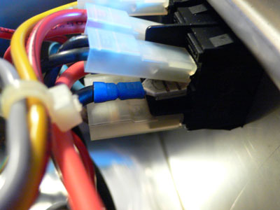
The installation method is very similar to the previous installation. The brew thermostat (red arrow) is bypassed by removing the connectors and extending them down to the SSR:
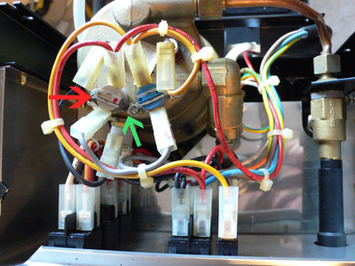
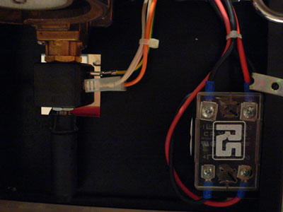
The thermocouple was remounted by carefully clamping it under the thermostat mounting screw (green arrow). The mains power for the controller was again picked up from the mains switch using elbow connectors:
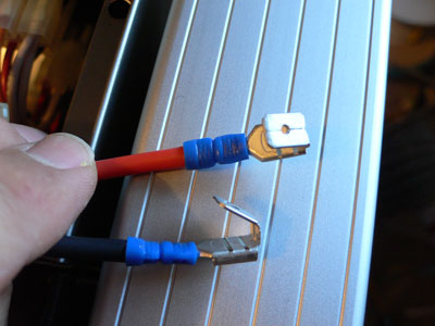
These slide onto the mains switch and the original connectors then slide onto the elbow:
The SSR was left in the same mounting position behind the front plate as before. Make sure you buy the insulating cover when you order your SSR:
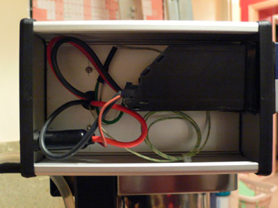
The major difference is using an aluminium project box, with fixed mounting to the side of Silvia and the wiring fed directly through the side of Silvia. The aluminium box is a Hammond box available from Maplin. Although not a perfect match for the stainless steel of Silvia, it's readily obtainable and easy to work with. The box is mounted to the black metal "spine" of SIlvia using M3 metal standoffs. It is vital to ensure that the project box is well earthed to the body of Silvia for safety. A larger hole must be drilled for the cables, carefully line up the hole in the project box with the hole in Silvia's spine. Make sure you grommet the holes to protect the wiring from chafing:
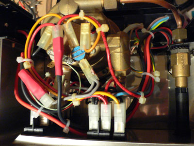
The wiring should be carefully zip tied to ensure it doesn't come into contact with hot parts, and also to stop it pressing on the top plate:
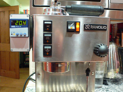
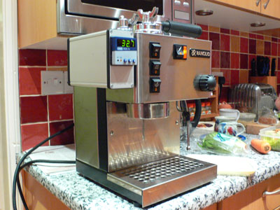
All put back together, I think the effect is reasonable for the effort involved: