Since AutomatedHome seems to have a bit of a Node-0 fetish, I thought I'd better show some pictures of my Idratek Node-I !
Here's the whole set-up. The two Hager CUs were previously installed to allow all lighting to be star-wired, the original intent was to use DIN mounting X-10 modules. So this was done before UKHA2003, when I discovered Idratek:
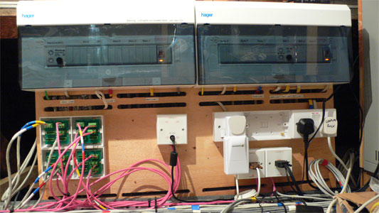
I still intend to use the CUs, currently most circuits are connected up in "normal" fashion using DIN-rail terminal blocks, but I do have 2 LD11s for room dimming and a couple more in boxes waiting. Idratek have DIN-mounting relay blocks, which I will be trying out shortly, but currently no DIN-rail dimmer. I fully expect that to be rectified. In the meantime, the LD11s can be integrated into the Idratek system via the X10 gateway, so I use those.
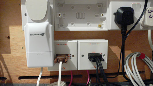
Underneath the CUs is Node-I proper. This consists of the patchbay and gateway sections.
The patchbay is made from 4 Idratek patch modules (6WA001) removed from their faceplates and reverse-mounted into surface mounting twin pattress boxes. The 4 patchboards each provide 6 connections, and given the capability of the modular connector to join multiple cables, and the arbitrary Idranet cabling topology, I fully expect this to be sufficient. The use of 4 sections matches the 4 outputs of the MPD-001 mini power module, and also the segmentation in the battery backed IPS-001 intelligent power supply. I've left a gap to allow an upgrade from MPD-001 to IPS-001 later.
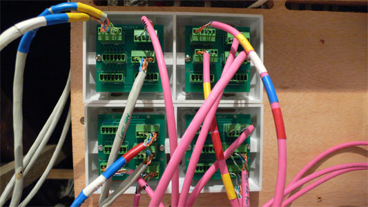
As you can see, I'm mostly using pink C-Bus cabling, together with a bit of screened Cat-5 that I used before the C-Bus stuff became easily available. Note the cable markings using coloured tape - probably the first of many useful things I learnt on the AutomatedHome site.
Before this photo was taken I started terminating with a Krone box. This turned out to be far more trouble than it was worth, and was removed. I guess the cable routing is a little untidy at the moment, at some point I will sort that out.
The gateway section consists of the XGW-001 X-10 gateway module connected to the CM-12U X-10 interface, which is plugged into a dedicated socket outlet. To the right of that is the PCA-001 PC gateway with audio functions. This connects to the PC that runs the Cortex application. Many people have commented that the CM-12U interface is unreliable, but I have not had any problems so far (although, now I've blogged it, it will probably fail).