Just in case you've been wondering why it's been so quiet round here, I've been working up the courage to start cutting holes in the bathroom ceiling. Since the bathroom is "finished", there is no margin for error.
The goal for the bathroom was to automate 3 lighting circuits: main, sink mirror and shower, and also the shower fan.
The shower fan originally had a humidistat switching the 12V from it's safety transformer. The theory was that it would only run "when it was needed" - this was based on the advice of a former colleague. The internal workings are based around some kind of woven material, which presumably goes slack when it's wet and releases the switch. Something like that, anyway. Frankly, it was rubbish. Whenever the weather was a bit damp the thing would run all night. But if you wound up the humidity level, it wouldn't run when you had a shower. Of course, I could have replaced it with timer operation, but I refused to be beaten.
So, the double box was replaced, with a bit of careful cutting and judicious use of the vacuum cleaner, with a twin box, into which Iwas installed a THS-001 temperature/humidity sensor and a DRB-001. The worst part was pulling the cables through, much crawling around under the eaves, banging of head, skinning of elbows later:
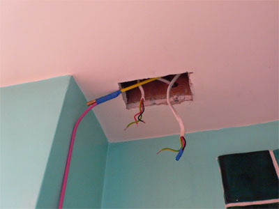
The DRB-001, in common with all the mains switching modules, includes a vacuum formed cover for the LV connections to provide the segregation required by the wiring regs. This cover can make things quite tight using 25mm deep boxes, especially if you have any spare circuits or junctions (eg power main feed) to make, or if the idranet cable doesn't feed up from the bottom. So, if in doubt, fit 35mm (or deeper) boxes when possible:
The usual module configuration procedure was whizzed through - as usual I preconfigure on the desk. Fairly conveniently, Tamzin decided to have a shower, which gave me a pretty good baseline to chose the humidity thresholds:
Setting this up was exactly analogous to the temperature controlled fan in the loft, although you can choose thresholds by relative humidity or by dew point.
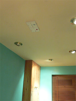
In accordance with my standard approach, I also installed an LPS-001 (light level and PIR) in the ceiling. The ceiling in this room is fairly busy, so choosing a good spot was a little tricky. In the end my chosen spot is not quite optimal, since it picks up movement on the landing if the bathroom door is open. I don't think it is a big deal, since about 50% of the time that traffic will be going into the bathroom anyway.
Alongside the LPS-001 is an IRM-001. This is an infra-red receiver only, slightly cheaper than the ITR-001 transceiver - I doubt that there will be anything to control via IR TX in the bathroom (for obvious reasons) so it seemed a sensible choice. If I'm wrong it will be easy enough to replace. My intention is that this will allow control of the main light dimmer (and also sound source when the ceiling speakers are fitted) from the bath:
The lighting circuits were already star-wired back to a CU in the loft. The original scheme has the 3 light switches in a double box on the landing. This was done to allow the use of a MK grid system dimmer for the main circuit. However, it turned out that the grid dimmer was not man enough for the job, and it was replaced with an LD11 X-10 dimmer in the CU. So, conveniently enough, I can quite happily change the double box back to a single and use a QBI-001 unit to control the switching:
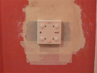
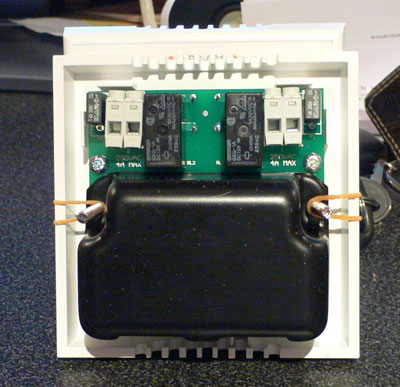
The sticky tape is to hold the dust in until I do the stopping up. Since I've dead-legged the switch wires at the CU, there's no mains voltages poking about here. Here's a close-up of the QBI to show the barrel distortion on my camera:
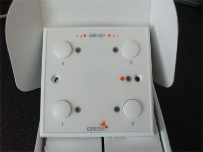
All the single modules are actually perfectly square and perfectly flat, since they use a common moulding with a changeable faceplate to customise them to their function. Well, maybe not "perfect" for the mathematically purist reader or anyone in QA.
Since the QBI-001 is buttons only, all the switching is done in the CU, the main circuit remains on the LD11, the subsidiary circuits are switched using a QRI-002 4-way DIN rail relay unit. This uses a fairly generic 3rd party DIN rail box, which is understandable, given the cost of custom moulding, but it doesn't have quite the feel of some alternatives. To be fair to the Idratek guys, this unit is very new and has been supplied with a temporary faceplate so that I didn't have to wait. It's going to be hidden in a CU anyway:
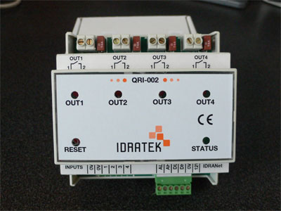
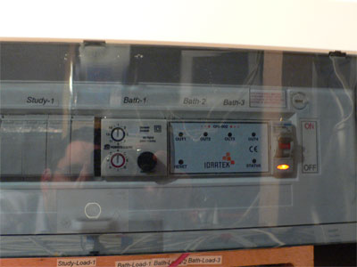
Nothing very much to say about the QRH-002 installation, pre-configured on the desk, wired it in, set up the relay connections and away we go. Here's a rather bad picture of the CU with LD11 and QRH-002 -- if you look really closely you can see my reflection:
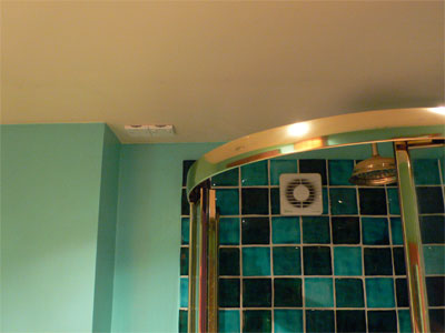
So, to finish on a high note and partially restore my photographic credentials, this is a long range shot of the THS-001 and DRB-001 next to the shower cubicle:
A later article will examine the IR remote control set-up.