I've been working on default reflex behaviours to provide back-up functions if Cortex is unavailable. So far I covered the simple direct switching case and a more complicated 3-way remote switching example. The most complicated behaviour required for my backup lighting control is to handle X10 dimmers via Reflex from the DRB panels.
There are two problems to be solved for this scheme. Firstly, there are no built-in toggle commands for X-10 control like there were in the Idratek modules, and so state tracking will be necessary. Secondly, the command insight editor's insight stops at the XGW X-10 gateway, it does not provide X-10 packet building capability. It's a bit of a mystery to me why it does not, since the database will contain information on the X-10 devices and their addressing and capability, and Cortex can obviously build X-10 packets for it's own purposes. So I have to assume it is an omission based on feature priorities, rather than technical feasibility. What is more, the Cortex help doesn't seem to cover building X-10 packets either, so a bit of experimentation is required.
The first thing to do is to understand the XGW and how packets are sent though it. Since it forwards X-10 information to a CM12u, it is actually the CM12u protocol we need to work with, rather than the "on-the-wire" X-10 protocol. I always struggle to find adequate and correct documentation on X-10, but one fairly good document is here.
The LD11 dimmers I want to control have a "memory dim" function, such that the ON command returns the dimmer to the last brightness level before the unit was turned off. For simplicity, I want to have a simple full on, full off effect, rather than dimming control. So, since I do not know the prior level, I need to send a "Bright" command with maximum level, rather than "ON". However, OFF is always OFF, so I can use that. One way to do this is to send a "Bright 22" X-10 command. Since 22 is the maximum, this guarantees the LD11 will be set full on, whatever it's current or memorised level.
So, to turn the dimmer (address A2) into a glorified on/off relay, we need "on" and "off" X-10 packets:
X-10 On (Bright 22)
Address Header:  04 = < 0 (ignored) >1<A><S>
          Code:  6E = <      A      ><  2  >
Function Header: B6 = <      22     >1<F><S>
           Code: 65 = <      A      >< Bri >
X-10 Off (OFF)
Address Header:  04 = < 0 (ignored) >1<A><S>
          Code:  6E = <      A      ><  2  >
Function Header: 06 = < 0 (ignored) >1<F><S>
           Code: 63 = <      A      >< Off >
For testing, the complete Reflex packet is built up in the command insight as usual, addressing the X-10 gateway and using command 52 (send X-10 packet), followed by the X-10 packet designed above. Since my gateway has address 0030, the final Reflex packets are:
FA900030440052046EB665
and
FA900030440052046E0663 respectively.
The second problem is to create a toggle effect in order to decide which packet to send. The initial state of the light will not be known (since it will have been under Cortex control and there is no feedback from an LD11 via X-10), so I arbitrarily assume it is off and the first command will be the ON command designed above. The next time the button is pressed, the OFF command should be sent instead.
Clearly, we need to do more than just send the ON/OFF packets. In fact we need to have something to track whether the light is currently on or off (technically called the state variable) - remembering that the LD11 doesn't support any direct feedback - and then a conditional operation to select either on or off based on the value of the state variable.
The easiest way to maintain the state variable is to use a bit in the UDRCF (User Defined Response Condition Flags). This is effectively a memory location that is implicitly addressed, so no memory mapping is required, it acts lik e a named register. If none of the previous sentence made any sense, just think of it as a place that you can keep bit settings and refer to by name.
The DRB supports a single byte UDRCF, but multi-byte UDRCFs are possible in some modules. Once we have a state variable, we then can use a conditional operation to test the value of the variable and send the appropriate packet. So a psuedo-code might be:
IF UDRCF-bit-0 = 0 THEN  SEND X-10 ON
IF UDRCF-bit-0 = 1 THEN  SEND X-10 OFF
TOGGLE UDRCF-bit-0
This psuedo-code reflects both that there is no "IF ... ELSE" construct in the Reflex command codes and that a direct toggle operation is available that can act on the UDRCF in a bit-wise fashion.
Starting to translate this into the Reflex commands:
First command:
E3 - Bitwise NOT AND (Par1, Par2)
00 - Par1 is UDRCF
01 - Par is literal value 01, ie a bitmask 0000 0001, we are using lsb of UDRCF as our state variable
FF - Send network packet
90 - NMF - packet type and network mode
FF - auto fill TX address high byte with actual module address
FF - auto fill TX address low byte
00 - RX address high byte (ie 00 from XGW 0030 address)
30 - RX address low byte
44 - ACK requested, 4 repeats
00 - 1 length byte
[NB - packet length bytes are automatically inserted by transmitter]
52 - XGW command "Send X-10 packet"
... the calculated X-10 packet for ON
Similarly the next line
E2 - Bitwise AND (Par1, Par2)
00 - Par1 is UDRCF
01 - Par is literal value 01, ie a bitmask 0000 0001, we are using lsb of UDRCF as our state variable
... as before, but use "off" X-10 packet
And then toggle the UDRCF bit 0:
0C - Modify UDRCF
30 - 3 = toggle operation, UDRCF 0
01 - bit mask for bits to toggle, ie toggle lsb
A Reflex program is built in segments, with the complete program terminated by an 00 byte. A segment, roughly corresponding to a line of psuedo-code above, is introduced by a length indicator to define the number of bytes following.
So our Reflex program to be executed in response to button 1 release consists of three packets:
2EE30001FF90FFFF0030440052046EB665
2EE20001FF90FFFF0030440052046E0663
030C300100
Cortex will manage the insertion of the length and terminator bytes, so we'll only need to define the part in bold.
The first thing to do is define the packets related to the X-10 gateway. This is where I think Cortex becomes a little confusing. If you attempt to define the packets against the DRB module, you find that there is no "Define Packets" button. If you try to define them against the "buttons" sub-function, you are redirected to the "switches" as a combined sub-function. If you then try to define them against the "switches" sub-function, there is again no "Define packets" button.
But, if you then try to define them against, say, the XGW (since you are sort of sending them there), the defined packets will automatically have erroneous addressing appended, irrespective of selecting packet only or packet + header mode when defining them.
However, I discovered by accident a method to do this. It's a little bit roundabout and perhaps there is a better way *update*. But anyway ...
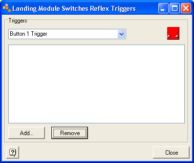
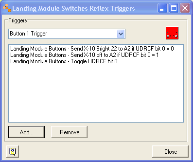
Select DRM Switches Module > Cortex Context Menu > Reflex > Vector Setup. Now select Button 1 as the trigger from the drop down. You should be here:
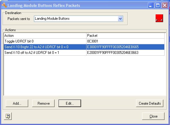
Then select Add and then "Define New Packet". From the drop-down you can select the DRB module, in my case this is "Landing Module Buttons". So we are now defining packets against the Landing Module Buttons, but can't get there directly from the Buttons Reflex menu :-)
Use the "Add" command and enter the packet:
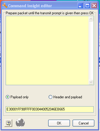
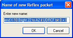
Next give it a meaningful name:
Define the other two packets in a similar fashion. At then end you should have three packets defined against the "Buttons" function.
Then close everything back to the "Define Vectors" dialog. Now we actually define the Reflex program we want associated with the Button Trigger by adding the packets in the order defined:
Next, we Reflex program the DRM module as before.
We can check that the Reflex program is as intended. First, use the "List Whole Network Reflex Program" from the tools menu:
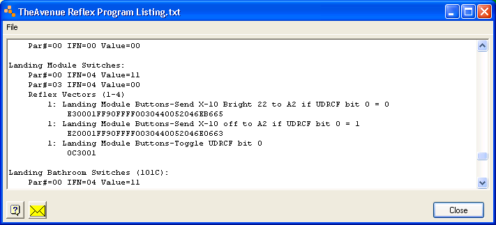
Note that all packets are associated with vector 1, this is equivalent to Button 1 being pressed and the length and terminator bytes have been automatically added.
The other thing we can do is use the Node Profiler Utility to have a more detailed look:
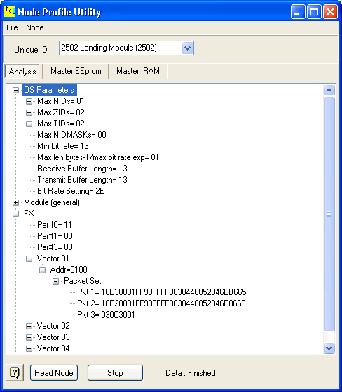
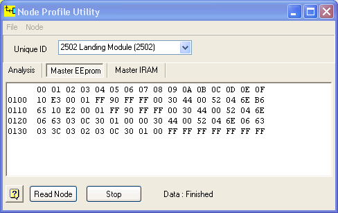
What this reveals is that Cortex is managing the EEPROM storage and automatically saving the program from address 0100. We can read back the EEPROM to double-double-check:
To test the program, we could stop Cortex and let the watchdog reset the nodes into the default program. However, since Tamzin will get annoyed if the lights go out, instead I network disable the Landing Light (LD-11 A2) and landing DRB module and then reset the module. The function can then be tested.
I have to say that getting this working did cause me a bit of frustration. Cortex support could be better and I tripped over a few things on the way. Since an incorrect reflex command may well "hang" a module, Cortex insight editor support is important in order to get things correct, but, as far as I can tell, it is currently incomplete, at least for the program I was generating. Having said that, the method above works around these problems and creates a satisfactory Reflex program.
Of course, once an Idratek DIN rail dimmer is available, all of this will be unnecessary ...
Update
I have found that the packets can be defined against the "Relays" sub-function of the DRB and work correctly. Similarly, for a QBI, which doesn't have "Relays", the "LEDs" sub-function can be used. So the trick is to define them against an "output" function for any module. I still think that this is a bit confusing, since there's no relationship to the Relays, but there is to the buttons or, arguably, the whole module.