Looking back I realised I never talked about some of the fundamental concepts in Cortex. This is the first of what will probably be a series of articles to explain some stuff.
Cortex is object oriented, which probably doesn't mean much if you are not a programmer, although for a while it was the most important buzzword in IT. What this means is that Cortex represents "stuff" as "objects". Hmm, maybe that didn't help.
OK. Let's say I've decided to automate a light bulb. I've got my light bulb and I have wired it up using copper cable to mains power with a relay module to turn it on and off. The relay module is connected the the Idranet cabling and eventually back to a computer running Cortex. On the computer I am running Cortex software and I need to define configuration of that software to determine when to change the relay and hence control the light bulb. We'll come back to this later.
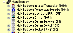
In Cortex, when you add a new module to the Idranet it is detected and it's basic properties can be configured. This will create an object in Cortex that represents that physical module and it's essential properties, like it's network address. Corresponding icons will be created on the floorplan and they will also appear in the tree structure. Here's some objects in my bedroom:
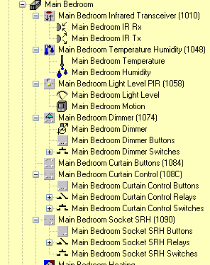
Cortex refers to these as Idratek Network Objects. At this level they represent individual physical modules. But the different types of modules have various capabilities, different sensors and actuators, like temperature sensors and IR transmitters or relays. So you can expand the tree to see the capabilities on the various modules:
These sub-functions are really what is interesting, the parent object that "owns" them is really representing the network connection and physical placement of the module, it's these sub-functions that do the work. Various types of modules are available with different combinations of these functions, but the sub-function will always be represented in the same way in Cortex and have the same capabilities, irrespective of the module it is on*.
In fact, these sub-functions are also objects in Cortex. Each one will add an icon to the plan view, although to avoid it getting crowded they can be hidden.
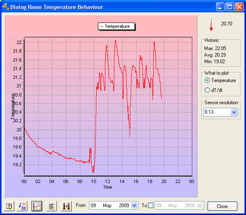
Let's think about a temperature sensor. The physical temperature sensor on a module is going to produce some kind of signal to represent it's temperature measurement. The module will perform some basic processing on this signal to convert it to an accurate value in degrees celsius. But even that isn't very useful in itself. Cortex also provides a bunch of functions in software that can scale and offset this value, log it and graph it over various time periods, set various thresholds that can trigger other things, and so on.
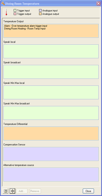
So the object for the temperature function is representing both the physical temperature sensor in the module AND a bunch of software in Cortex to do useful things with it. The bunch of software can be configured to process the temperature measurement through the behaviour dialog for the temperature object:
But this isn't sufficient, to be able to do something useful with these processed temperature values we need to connect them to other objects. This is done through the connections dialog for an object:
You can see in this dialog that the temperature object has input and output connections. Input connections on one object can be connected to output connections on another object. Output connections can connect to inputs on more than one object, as you can see above. These are purely software connections, they don't mean that a wire has to exist between the associated physical modules.
Input connections will modify the behaviour of the object. Output connections can be made to modify the behaviour of some other object. So here you can see that the temperature output value is fed to the alarm object and the dining room heating control.
There are also two types of connection, triggers and analogue values. Analogue values typically pass the value of a measurement, like the actual temperature. Trigger values initiate some action or turn something on or off. So, for example, pressing a button can create a trigger output that can be connected to another object trigger input to make something happen.
So far we have seen objects that represent physical modules, or aspects of physical modules with some additional software functions. There are also objects that represent purely software functions that have no corresponding hardware modules. Cortex calls these Cortex logic objects. An example of a logic object is a macro. This can have connections to other objects and it's behaviour will be the macro executed on a start trigger. Another example is the room object which represents the presence detection logic implemented in Cortex that takes many inputs and configuration information to determine where people are.
There's another type of object. I'm not sure it has a name in Cortex, but let's call it a device. A device object represents an external physical object connected to an Idratek module and some software functions to handle it, in a similar way to the temperature object discussed above. Now Idratek can't anticipate every possible thing that you might connect to a module, but they can represent common ones, like screen motors and alarm strobes, and also provide a "catchall" device object effectively representing a vanilla module input or output.
There are only a few types of physical module connections available, basically digital input and output and analogue input or output, these are the device objects available for each type of physical input/output.
|
|
Relay or Digital Output |
Switch or Digital Input |
Analogue Input |
Analogue Output |
|
Catchall |
On/Off Load |
Digital Input |
Analogue Signal |
Analogue Load |
|
|
Light |
Door |
|
Light Dimmer |
|
|
Heat Zone Valve |
Bell Push |
|
Analogue Heat Zone |
|
|
Boiler |
PIR |
|
Analogue Cool Zone |
|
|
Alarm Bell |
Pulse Count Meter |
|
|
|
|
Alarm Strobe |
Proximity Detector |
|
|
|
|
Cool Zone Damper |
Button |
|
|
|
|
Air Conditioning Unit |
|
|
|
|
|
HVAC Slave |
|
|
|
|
|
Motor Relay |
|
|
|
So given an available digital input connection, you might connect a magnetic reed relay. When the relay is closed the input will read low and when open high. If the Digital Input device object is used then Cortex will show the input as high or low and record it's history in those terms. However, if you mount the reed relay on a door then you might choose the door device object. Cortex will then represent a door icon with open and closed states. Although this is a trivial example, some of the device objects package up a lot more functionality.
So back to the light bulb. I'm going to end up with several objects in Cortex: The object representing my module, say it's a DRB. Another object represents the relay on this module. And underneath the relay is a light device object representing the light bulb and the logic to determine when to turn it on and off.
*an exception to this is related to pulse count monitoring. Not all modules with digital inputs can support this function.

Leave a comment